I have had a Sample and Hold for a long time...

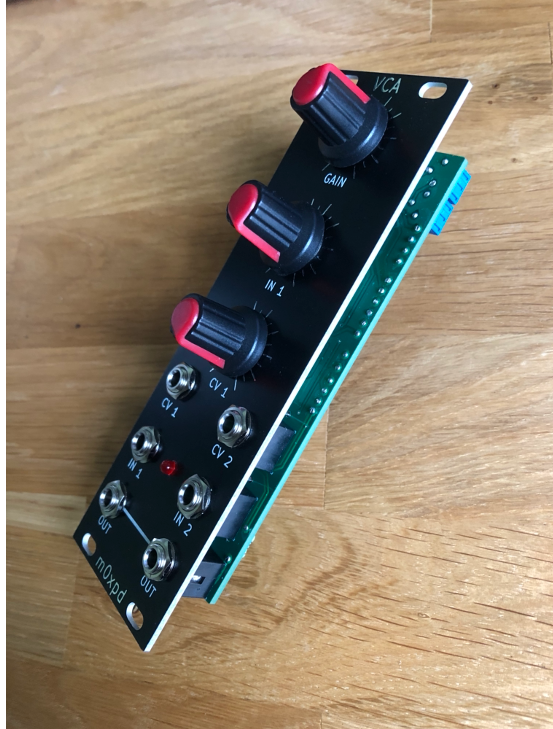
It is, as you see above, a homemade module, built around five years ago to the design published by the late, great Ray Wilson of 'Music from Outer Space'.
I decided - for reasons I'll explain in a moment - that I need a new Sample & Hold.
There are a number of reasons why you might want a Sample and Hold ('S&H') in a synthesiser, of which the two most common seem to be:
1) the generation of random sequences by sampling noise (or some other varying signal)
and
2) "bitcrushing"
The generation of random sequences is a nice problem, which we'll look at first, by a practical example:


The Sample and Hold system certainly has bitcrushed the nice triangular signal of case 1 by the time it gets to case 5, whatever you take bitcrushing to mean!
There's another reason I like using sample and hold devices, different from the two "standard" examples above. It is to extract notes from sequences. To extract - if you will - a sub-set from a set.
Here's the example:

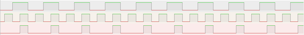
In the oscilloscope screen grab above, you see part of a pitch sequence coming from one of my sequencers, (and so ranging between 0 and 5V, seen on the channel 3 trace in magenta) and samples of that signal, captured (sampled) at a regular rate and held between these sampling points (seen on the channel 4 trace in light blue). These channel 4 values are individual 'notes' from the channel 3 pitch sequence, selected at the times the sample and hold is triggered. In this case, channel 4 is sampling one in four of the 'notes' on channel 3.
I like to use these notes as "pedal notes" or notes for bass voices to play whilst other voices play the faster sequence (in a higher octave). It is an easy way to build harmony.
I have been using my old MFOS S&H module to do this for many years, but was irritated by two of its "features".
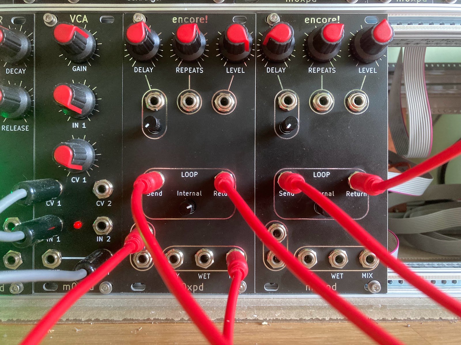
Firstly, it has front panel adjustments which allow you to apply gain and offset to the sampling process. These are controlled by the two knobs closest to the array of sockets (see the photo at the head of this post). To use the device in my "pick a note out of a sequence" application, it is critical that the sample and hold has exactly unit gain and no offset.
But every time I plugged something it, I couldn't help touch the knobs that displaced both these settings. This meant that every time I used it I had to re-set, costing time and irritation!
Also - to be honest - my MFOS sample and hold module does suffer a little 'droop' in its hold phase, as charge on the hold capacitor leaks away over time.
So - my plan was to address these issues in a new unit, with NO FRONT PANEL ADJUSTMENT for gain or offset, and better hold performance.
I started off with a re-spin of Ray's MFOS unit, which uses a C-MOS 4066 analog switch to switch charge onto the hold capacitor. I had a prototype of this new circuit working pretty quickly and quite well enough to "go to production", but my attention was caught by the simplicity of Moritz Klein's S&H. This design, which features both in Moritz' YouTube video and in the Erica Synths ".edu" module, uses a FET to switch charge. I felt I ought to give this approach a whirl too.
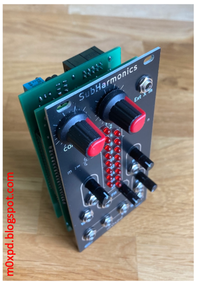
As readers already know, I am a big fan of Moritz Klein, having used his VCO core in the SubHarmonics module and identifying his important pedagogy in synth DIY. Moritz is explicit in calling out the limitations of the FET in this application, but he surprised me by saying:
“If you want to sample a tuned sequence for your VCO for example, you’d absolutely need precision, otherwise it would sound way out of tune. But that’s a very specific and, frankly, not that practical use case, at least from my perspective.”
(M Klein, Designing a sample and hold circuit from scratch, 16:31)
So - Moritz thinks that my application is a very specific and not that practical use-case, which would absolutely need precision!
Hearing that, I felt it was OK to give up on the FET (which at that point I had working as well as the analog multiplexer) and look elsewhere. I needed to look no further than Eddy Bergman's site, where a recent post described a sample and hold derived from a design by Rene Schmitz. These used the LF398 device - an application-specific S&H chip.
The LF398 sounded way too expensive for somebody like me - a cheapskate who had been messing around with CD4066s and J113s. But I took a look on our favourite auction site and found some LF398s for about £1 each. I set one up in the same breadboard I'd been using with the analog switch and the JFET and suddenly everything got a lot easier!
So - a new sample and hold module is born...